A sleeve is defined by the relationship between its inside and outside surfaces. Turning creates the outside steps, bore and seating faces; a mill-turn route can also bring cross holes, flats or other side features into the same component plan where access and tooling allow. We examine how the bore locates, how a shoulder seats, and which finished surfaces matter to the mating assembly.
01
Turned axes and mating faces
The central bore and outside diameter may share a datum axis, while an annular face controls how the sleeve seats. Thinking about them together helps identify a production and inspection sequence rather than treating each measurement as an isolated number.
02
Milled details on a turned body
Some bushings need a side hole, flat or relief in addition to turned surfaces. Suitable mill-turn tooling may combine these features in a route, but a deep internal profile or restricted access can require a different setup or process.
03
Protect the finished interface
The drawing can distinguish a cosmetic area from a functional bore, shoulder or seating face. We consider finishing and handling requirements against that distinction, including whether dimensions apply before or after a specified treatment.
PHOTOGRAPHED GEOMETRY
Visible bores, shoulders and flanges
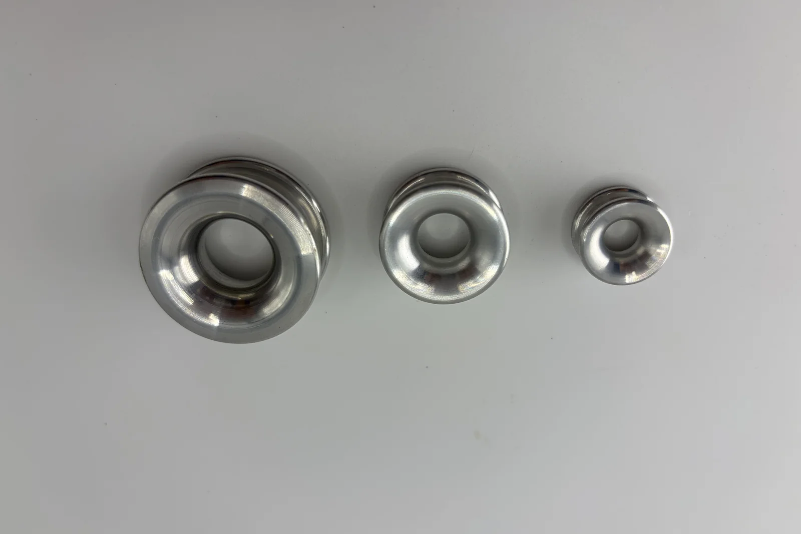
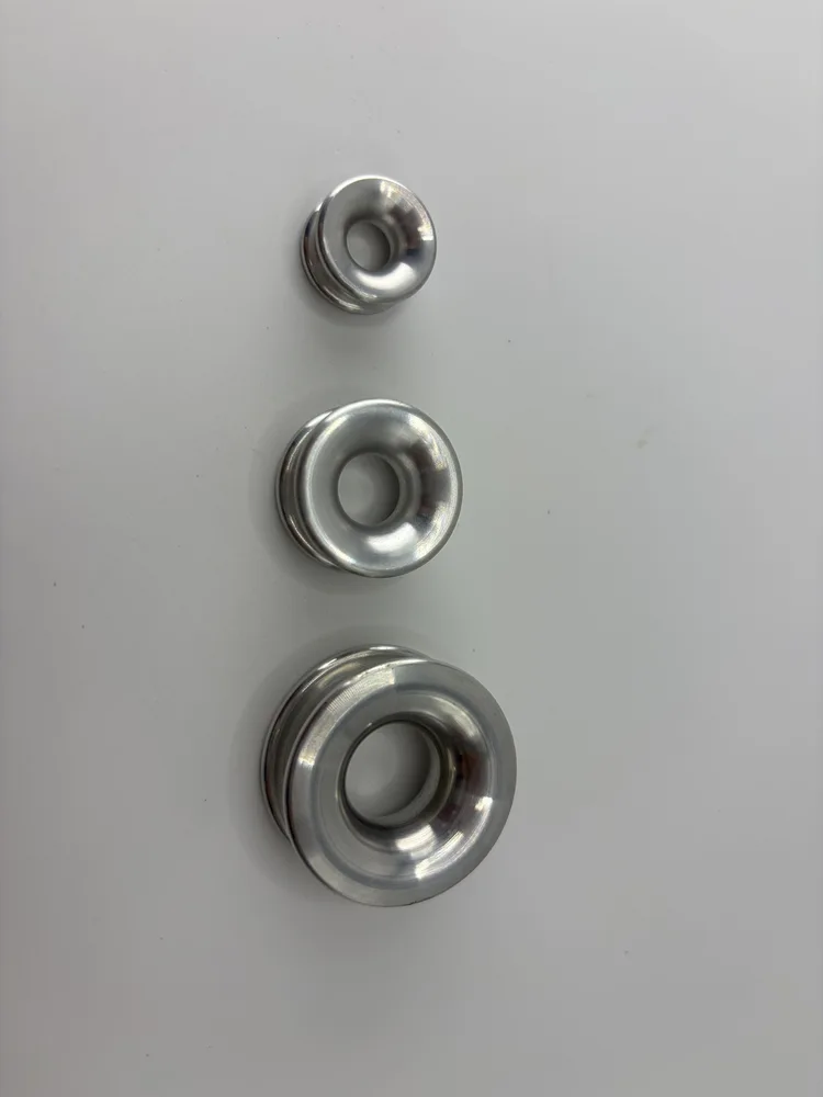
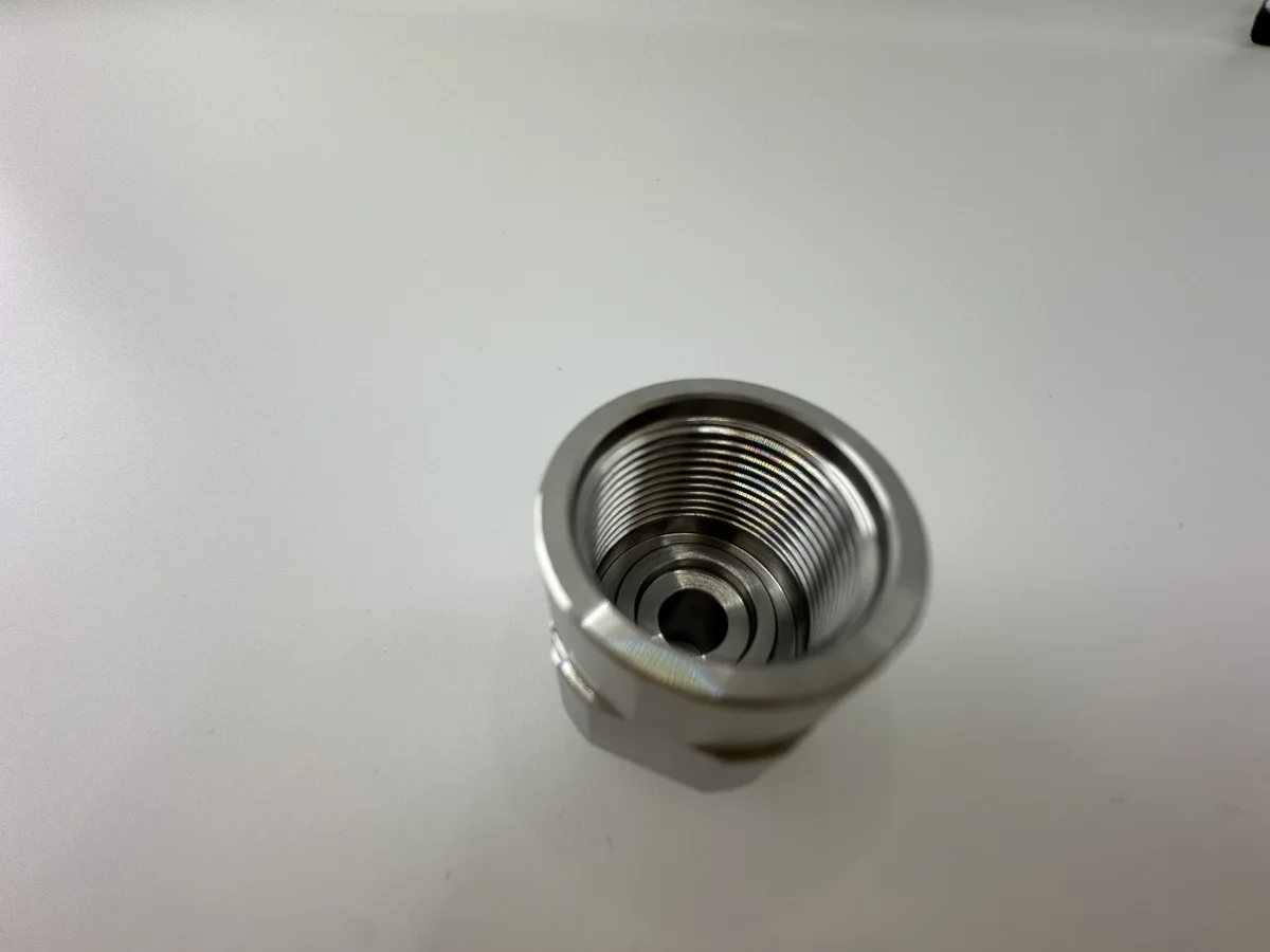
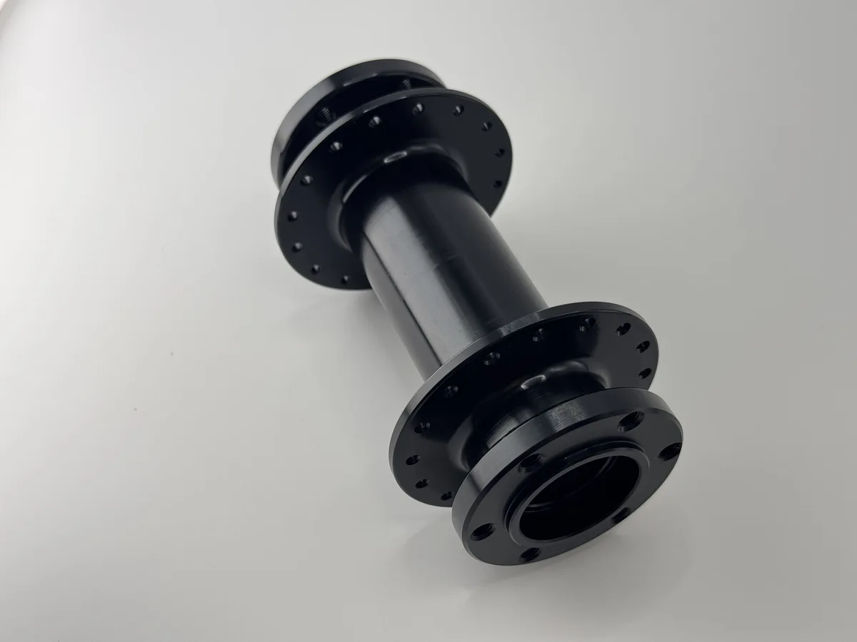
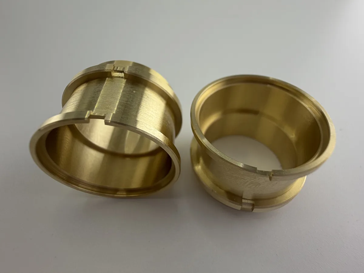
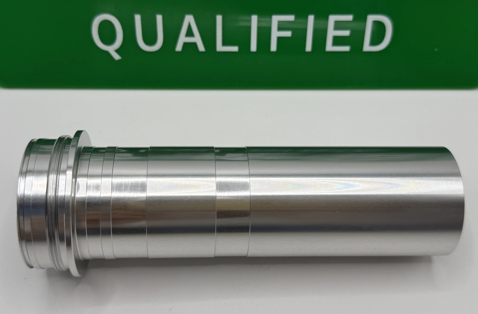
Parts photographed in our factory show three forms in the sleeve family: ring-shaped stepped sleeves, an internal bore with a step, and a flanged component with circular features. The marked photograph identifies the central opening and adjacent faces. These visible details distinguish the bore, shoulder and outside surfaces involved in a sleeve inquiry.
The table gives our factory-wide outer-diameter, length and batch ranges. For sleeves, our review covers wall thickness, internal tool access and inspection of the bore and faces. Dimensions after surface treatment are part of that review when the drawing specifies a finish.
Repeated sleeves can benefit from comparing the same drawing at several batch sizes. One setup shared across 2,000 units has 1/10 of the setup share per part at 200 units. This comparison does not include bar stock, machining time, treatment or inspection; those remain part-specific quotation items.
Share of one fixed setup per part, relative to 200 pcs
200 pcs
100%
500 pcs
40%
1,000 pcs
20%
2,000 pcs
10%
Arithmetic of one fixed setup, not a price list. Material and cycle time per part do not fall the same way; your quote shows the actual price.
Include a controlled drawing, bore and outside dimensions, overall length, material grade, intended quantity and the faces that locate or seal. Mention any after-treatment dimensions or required records. The RFQ checklist can help coordinate those details with the purchasing team.
02
We review the complete component
We assess geometry, material, inspection and quantity together.
03
Receive a reply and agree the next step
We reply from info@nowcnc.com about the next step. Sending an inquiry does not place an order.
Can turning and milling features be combined on a sleeve?
Yes, when the drawing and tool access allow it. A sleeve can combine a turned outside diameter and bore with cross holes, flats or other milled details. The route is set by the full geometry and may involve more than one operation.
Which sleeve features matter for inspection?
The bore, outer diameter, seating face and shoulders define the main inspection points. We review their size and relationship against the drawing, including which surfaces locate in the assembly and which dimensions apply after treatment.
Can I request different quantities for the same bushing?
Yes. Send one revision and compare several batch sizes with the same material and acceptance scope. The smaller release and any repeat demand should be identified separately when you ask for a quotation.
5,000 sleeves delivered 20 days after the order, including the anodizing trials.
YOUR NEXT PRODUCTION RUN
Review your sleeves & bushings drawing with us.
Bring the bore, shoulder and outside form into one discussion. A similar photograph helps us orient the inquiry; your drawing determines the production and inspection requirements.