Internal thread
Define the thread designation, fit and usable depth.
 Get a quote
Part example 05
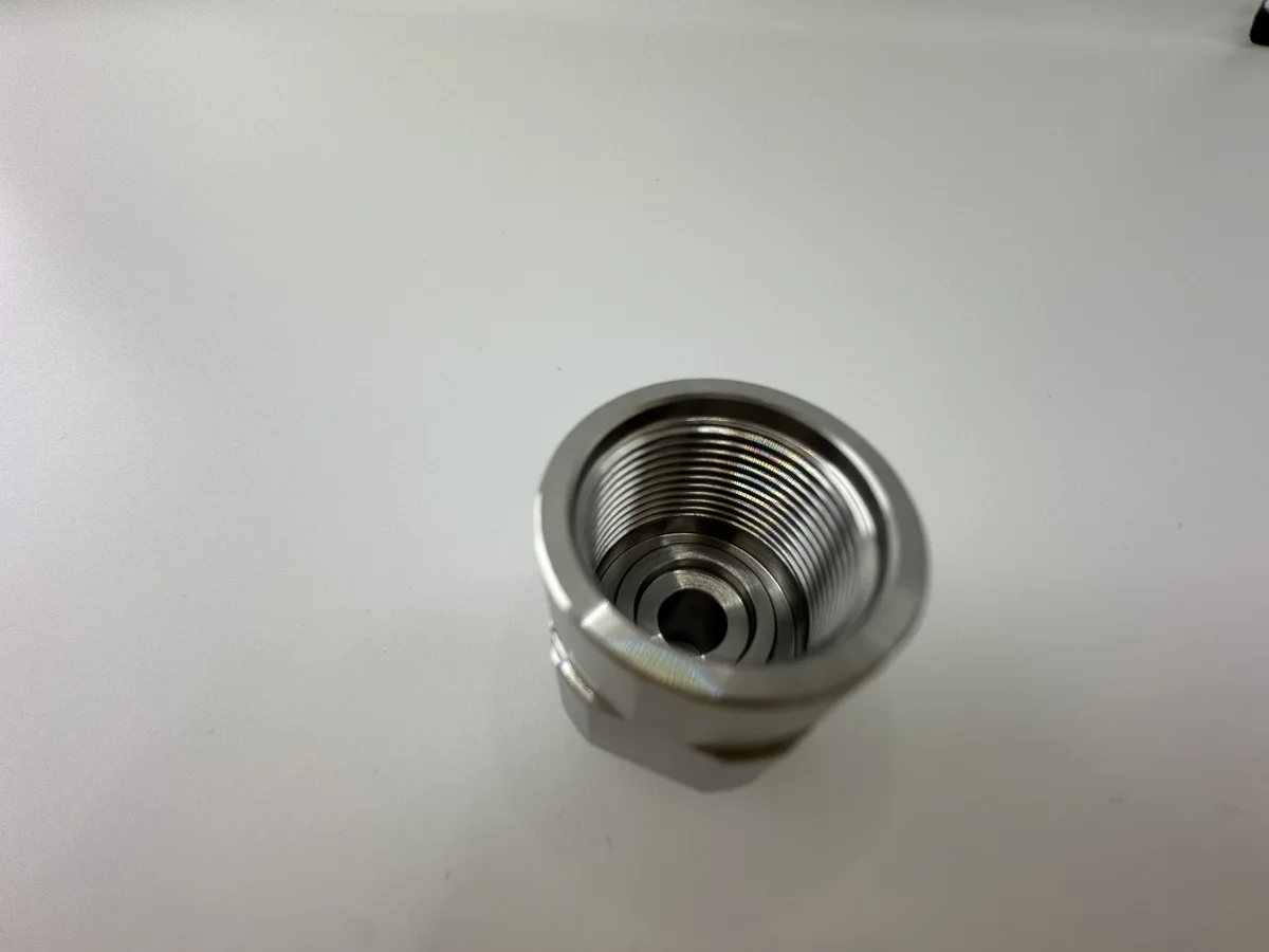
An internally threaded part with a stepped seat and a smaller opening. The cutting tool has to reach inside, and so does the gauge that checks it.
Define the thread designation, fit and usable depth.
Identify which surface locates or contacts the mating part.
Show the depth and relationship to the larger internal profile.
Deep internal features need room for both machining and verification. Define the complete section, including any internal relief, instead of dimensioning only the entry.
Thread checking, bore size and seat depth are different requirements. Agree which records are needed for each functional feature.
See inspection evidenceWe turn parts from 0.5–200 mm (0.02–7.87 in) OD and up to 300 mm (11.81 in) long, starting at 200 pieces. Our main focus is 1–100 mm (0.04–3.94 in) OD parts in runs of 2,000 pieces or more.
See how batch size affects priceThis photo shows a part we have made before. We don't sell it from stock: your drawing sets the size, material and finish, and we quote the part as drawn.
An internal thread, a recessed seat and a smaller central opening are visible. The photo does not reveal the complete section or depth.
| Visible feature | Process decision | Verification to agree |
|---|---|---|
| Internal thread | Review thread depth, tool access and clearance near the seat. | Thread acceptance against the specified designation and fit. |
| Recessed seat | Consider machining access and how its depth will be measured. | Seat depth and the requirements on its functional surface. |
| Smaller central opening | Use a section view to establish the complete internal route. | Opening size and its specified relationship to the larger bore. |
Tool access and inspection access need to be considered together. For internal turning, long, slender tools can increase vibration challenges; the geometry helps determine the appropriate approach.
Technical background: Sandvik: vibration challenges in internal turning. This source supports the general machining principle, not a measured result for this component.
Geometry analysis of the photographed component. Use the feature review to prepare your drawing and inspection requirements.