Stepped diameters
Define which diameters locate the assembly and how they share a datum.
 Get a quote
Part example 01
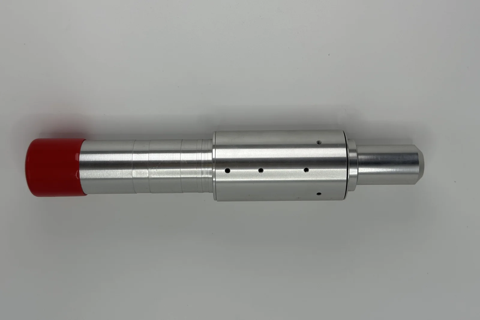
A stepped shaft with radial cross holes and an annular shoulder. Each diameter, the shoulder face and the hole positions need their own callout on the drawing.
Define which diameters locate the assembly and how they share a datum.
Identify the shoulder face used for axial location and specify the transition condition.
Locate the holes from a stated face and axis, including any required orientation.
If a radial hole must line up with a flat or another feature, its angular relationship belongs on the drawing. A photograph cannot define that relationship.
Connect diameter and shoulder measurements to the same drawing datums. Assess the radial-hole position separately from its size.
See inspection evidenceWe turn parts from 0.5–200 mm (0.02–7.87 in) OD and up to 300 mm (11.81 in) long, starting at 200 pieces. Our main focus is 1–100 mm (0.04–3.94 in) OD parts in runs of 2,000 pieces or more.
See how batch size affects priceThis photo shows a part we have made before. We don't sell it from stock: your drawing sets the size, material and finish, and we quote the part as drawn.
Stepped outside diameters, an annular shoulder and radial cross holes are visible in the component photograph.
| Visible feature | Process decision | Verification to agree |
|---|---|---|
| Two or more locating diameters | Select a shared reference for features that must work on the same axis. The drawing determines which relationships matter. | Diameter size and the specified relationship between locating features. |
| Shoulders and transitions | Review tool access and edge requirements at each transition before fixing the sequence. | Axial location, transition geometry and the condition of functional edges. |
| Radial hole | Decide whether angular orientation must be controlled relative to another feature. | Hole size and position from the agreed references. |
A diameter measurement alone cannot establish the complete relationship between two features. The drawing and inspection plan need to address the same functional relationship.
Geometry analysis of the photographed component. Use the feature review to prepare your drawing and inspection requirements.